Surface Finish Symbols for Engineering Drawings
Surface finish symbols are needed to represent the surface texture requirement to manufacturers. If you are working on CNC machining parts or some other manufacturing process. then you need to specify the surface finish requirement to manufacture. You can use surface finish symbols to tell the manufacturer about your surface finish requirements. In this article, we are covering what are the standards, and how you can select a particular symbol and the meaning of those symbols. if you have any doubts or any unclear thing please feel free to ask in the comment section.
Importance of Surface Finish in Engineering
When you are working on product design you need to think about the surface finish of the product. Sometimes, you have to think about particular surfaces especially due to the following reasons.
- Functionality of Components
- Wear Resistance
- Corrosion Protection
- Sealing and Leak Prevention
- Aesthetics view of the product
- Surface Texture and Grip
- Lubrication Efficiency
- Heat Transfer
- Adhesive Bonding
- Cleaning and Maintenance
- Electrical Conductivity
- Compatibility with Manufacturing Processes
You may have to think about all the above factors while you are working on product design. There are a lot of manufacturing processes to get the required surface finish. Depending on the requirements surface finish processes are different.
If you need a corrosion-resistant surface finish you have to deal with powder coating, hot dip galvanizing, Zink, Chrome, and other plating technologies. CNC machine parts require different surface texters and that depends on the object material and machining techniques. Shot Blasting, Sandblasting, Grinding, and Polishing are some other surface finish methods.
Each and every surface finish technique has different surface textures and you need to clearly define that requirement in drawings. So, now you need to know the meaning of Surface Finish Symbols. and
Surface Finish Symbol Standards
The Surface Finish Symbol Standards refer to the internationally recognized guidelines and conventions for representing surface finishes on engineering drawings. there are mainly two standards.
You can follow the above standards when you need to use surface finishing symbols for your drawings.
Then your next question is how you can use those symbols. If you are working on manual drawings you can draw those symbols by yourself. if you are working on design software then you have facilities to add those symbols to your drawings.
When we talk about the surface finish, surface finish depends on the surface roughness. For surface roughness there are standards.
- ISO 25178
- JIS B 0601-2001
Most of the design software has drawing facilities with those surface finish and surface roughness standards.
Commonly Used Surface Finish Symbols
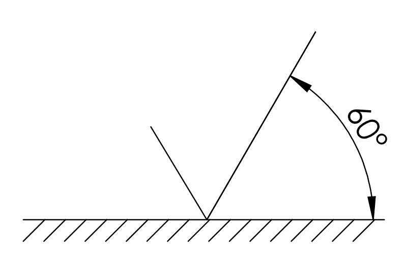
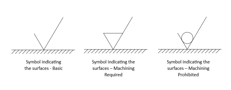
When you are going to add a surface finish symbol there are mainly three pictorial representations. The symbol indicates the target surface with two lines. Those two lines have different lengths with 60-degree angles.
Symbols for Machining Requirement
There are three symbols to represent the machining requirements.
How to Indicate the Flat or Round Surfaces
When you are working with a drawing you need to indicate the surface finish in flat and round surfaces. Then You can use the following Symbols.
For flat surfaces,

For round surfaces,

Surface finish call-out
A surface finish callout specifies the desired surface texture or quality for a particular part or component on an engineering drawing.

So, now you can add this symbol for your required surface in the engineering drawing. How to fill the Graphical Symbols?
Roughness Value
To fill the “a“, “f” and “I” values of the symbols you can use the below table. According to your surface roughness requirements, you can use these values.

Production Methods/Treatment Methods
Manufacturers are referring to the call-out to select the appropriate manufacturing techniques, such as,
- Machining
- Grinding
- Coating,
If you need some special manufacturing techniques you can add those in the letter “b“
Surface finish Symbols for Direction of Lay
The direction of lay means the pattern left by the cutting instrument on the surface. there are seven lay patterns.
Parallel to the Projection Plane

This pattern is made by an edge of the tool during the machining process. The tool direction is parallel to the surface. An example of this Lay direction is Shaped Surface.
Perpendicular to the Projection Plane

When the tool direction is perpendicular to the surface during the machining process this lay direction can be made. The following are some examples of Perpendicular lay directions.
- Shaped Surface – Lathe Operation
- Circular Cut
- Cylindrical Cut
Crossed in two oblique directions relative to the Projection Plane

You can see this kind of machining surface after the Honing process.
Multi Direction

If the machine tool has no particular direction or multi-direction, this surface can be expected. For Examples,
- Lapped Surface,
- Super Finished Surface
- Face Milled Surface
- End -Milled Surface
Particulate, Non-Directional, or Protuberant

This pattern has no direction.
Circular Relative to Center of Surface

This surface is more common for after-facing operations especially facing operations on lathe machines.
Radial Relative to Center of Surface

This is a radial pattern made by an edged tool during the machining process.
How to Use Lay Direction
You can use the following symbols to add lay direction.

Examples of Surface Symbol
Let’s think about your need surface finish with the following parameters.
- a – Minimum Roughness = 0.8
- b – Production Method/ Treatment = Grinding
- f – Maximum Roughness = 1,6
- d – Roughness Spacing/ Lay Direction = Radial

Really appreciate, taking the time to read the article about the Surface Finish Symbols. So keep in touch with MechHeart and feel free to add some comments here and share your knowledge with us.
Latest Posts;


0 Comments