Isometric Projection in Engineering Drawing
There are various methods used to present objects in both 2D and 3D views. One of the common types of 2D projection is the first-angle and third-angle projections. These projections provide different perspectives of the object by showing it from different angles. When it comes to 3D presentation, there are several options available. Isometric, Dimetric, and Trimetric views are the most common views. Isometric Drawing or Isometric Projection is the most commonly utilized 3D view in engineering drawings.
Proper knowledge about drawing views and drawing angles will give you a plus point. Not only that, Engineering Drawing Types, Drawing Lines, GD&T symbols, and Best Drawing Sheet Size are also important to designers.
What is an Isometric Projection Engineering Drawing?
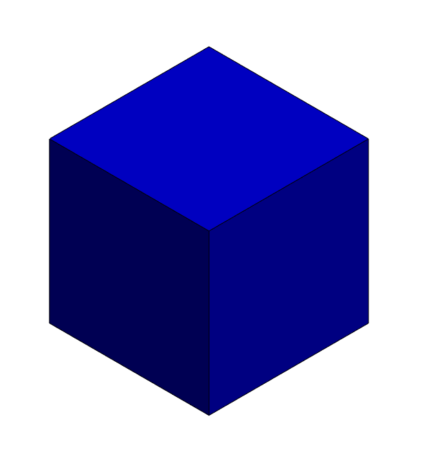
An isometric projection is a type of 3D representation of an object or a scene in which all three dimensions (length, width, and height). There are some specialties of Isometric Representation.
Key Characteristics of Isometric Projection
- All three axis lengths, widths, and heights have the same scale
- Lines representing the three dimensions are typically drawn at 30-degree angles to each other.
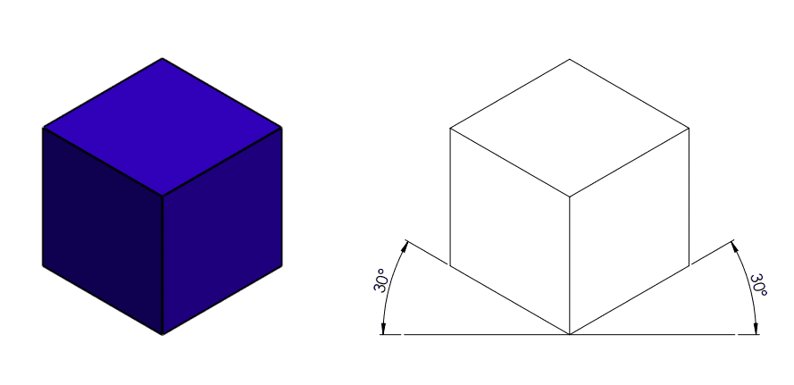
- Parallel lines remain parallel, and objects do not appear larger or smaller based on their distance from the viewer.
Isometric vs Dimetric vs Trimetric
There are three main 3D drawing angles. Isometric is the most common 3D Drawing View. The following table gives you a comparison of three main drawing views.

Isometric Projection Drawing Examples
When you preparing drawings for geometric models, You can add isometrics views in the drawing.

How to Draw Isometric Projection in Engineering Drawing
There are different Product Design Software in the market. All the software has drawing-generating facilities. Projection angle selection and 2D and 3D views are available in all the drawing templates of that software. When you use CAD or Product Design software, you can easily get 3D views.
If you need to manually create an Isometric Drawing View, The best way is to use an isometric grid.
Isometric Grid
Isometric Grid will save you time and effort. Using the below link you can easily download
What is the Best Location for 3D Views in the Drawing Sheet?
There are different drawing sheet sizes for the Engineering Drawings. At first, You can choose a drawing sheet according to your drawing type and requirements. After that, you can manage the paper for all 2D and 3D drawing views. There is no specific location to place the 3D view in the drawing. Based on the 2D views, tables, GD&T Symbols, and other notes, You can place 3D views anywhere in the drawing.
But as a common practice, you can standardize the location of 3D views for your all drawings. It will be smart practice in the competitive industry.


0 Comments