Orthographic Projection in Engineering Drawing
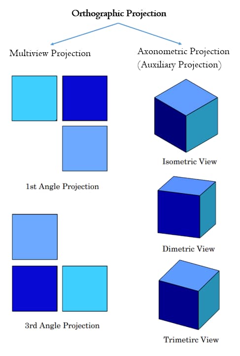
Orthographic Projection is a common technique to present a 3D object in a 2D way. It’s just not a single technique. It has mainly two types, like Multiview Projections and Axonomeric Projections. 1st Angle Projection and 3rd Angle Projection are also part of the Orthographic Projections.
When you are working on 2D drawings, you have to present your 3D object in a clear way. But how do you present the 3D abject in 2D projection views? How do you use the Orthographic Projection in your drawings? We will discuss all of these projections views one by one.
What is Orthographic Projection?
Orthographic Projection has two parts Multiviews and Axonometric Views.
What is Multiview Projection?
Multiview Projection has three common views, Top View, Front View, and Right Side View. But it depends on the drawing projection you selected for your drawings. However, before going to the drawing views you should select the Drawing Projection Angle. There are mainly two projection angles, 1st Angle Projection and 3rd Angle Projection.
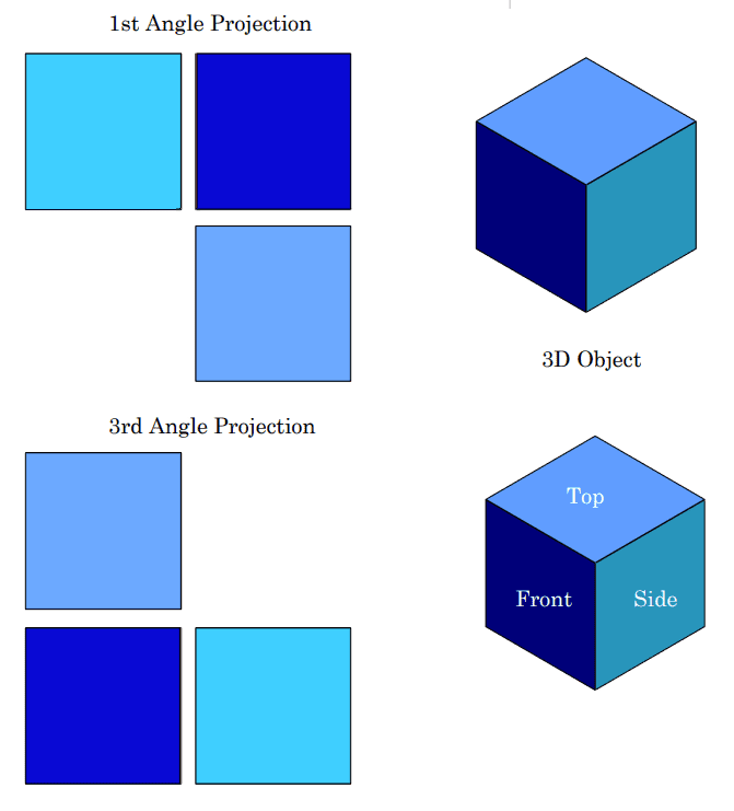
1st Angle Projection
The three main views used in first angle projection are the front view, the top view, and the side view. The front view represents the object as it appears when viewed from the front, while the top view represents the object as it would be seen from above. The side view shows the object as it would appear when viewed from the side.
- The front view or elevation is placed in the center.
- The top view or plan view is positioned below the front view.
- The right-side view or side view is placed to the left of the front view.

1st Angle Projection Drawing Symbol
The below symbol is the standard 1st angle projection symbol.

3rd Angle Projection
Third-angle projection is also known as European projection. The following are the basic features of 3rd angle projection.
- The front view or elevation is placed in the center.
- The top view or plan view is positioned above the front view.
- The right-side view or side view is placed to the right of the front view.

3rd Angle Projection Drawing Symbol
The following is the standard drawing projection angle symbol for 3rd angle projection.

Where you put your drawing symbol in the drawings. there are two common locations for the projection angle symbol. You can draw this symbol on the top left corner of the drawing or right bottom of the drawing.
Axonometric Views in Engineering Drawings
Axonometric views are a type of graphical projection used in technical and architectural drawings. It represents three-dimensional objects in a two-dimensional space. Sometimes this is called Auxilary Views. However, there are three main types like,
- Isometric Projection
- Dimetric Projection
- Trimetric Projection

Let’s see these projection views one by one.
Isometric Projection View
The isometric view is a type of 3D representation of an object or a scene in which all three dimensions (length, width, and height). This projection view has the following key characteristics.
- All three axis lengths, widths, and heights have the same scale
- Lines representing the three dimensions are typically drawn at 30-degree angles to each other.
- Parallel lines remain parallel, and objects do not appear larger or smaller based on their distance from the viewer.

For a better understanding of isometric drawings, please refer to our web article on the topic.
Dimetric Projection View
You can use Dimetric Projection Views for your drawings. But this is less common than Isometric Projection View. This projection view has the following key characteristics.
- Two of the three axes (usually length and height or length and width) are foreshortened at different scales.
- The third axis remains unaltered, which provides a sense of depth and dimension.
- This projection uses two different angles and it will give a more natural and aesthetically pleasing representation.

Trimetric Projection View
This is a less common projection view than the other two. when you need a high level of customization in design drawing, you can use this view.
- All three axes (length, width, and height) are foreshortened at different scales.
- Each axis in trimetric projection has a unique angle of projection.
You can vary the scaling and orientation of each axis to create a representation that best suits your specific needs.

What is the Best Location for Orthographic Projection?
The first thing is you should select a proper drawing sheet size for drawings. All the product design software has facilities to select the drawing sheet sizes. After you select the drawing sheet you can place the drawing views. There is no specific location to place the 3D view in the drawing. Based on the 2D views, tables, GD&T Symbols, and other notes, You can place 3D views anywhere in the drawing.
But as a common practice, you can standardize the location of 3D views for your all drawings. It will be smart practice in the competitive industry.
How to Increase the Quality of the Engineering Drawing
Orthographic Projection will not present all the manufacturing requirements in drawings. It will give only better views of the 3D object. So, you will have to use GD&T, Drawing Symbols, and Annotations. GD&T symbols are the key element to present the manufacturing requirements. You can use Drawing Symbols, Annotations, and Manufacturing Notes to describe the machining requirements. Other than that special symbols like Surface Finish Symbols, and Welding symbols are also very important.
Proper use of drawing lines, and hole specifications like counterbore, and countersunk also improve your drawing quality.


0 Comments