GD&T Symbols for Engineering Drawings
GD and T is stands for Geometric Dimensions and Tolerances. Most of the engineering fields are using different types of symbols. Those symbols are based on their engineering discipline and the country. Generally most of the symbols are common for all over the world. How ever, if you have some knowledge of those symbols and meaning it will very use full to understand the engineering drawings. Some GD&T symbols are based on the country and standards. However GD&T is used to define the geometric features in allowable feature limits.

To get the initial idea of GD&T you can read our article of “what is GD&T in engineering drawings“. Other than the GD&T there are some other drawing symbols like surface finish symbols, welding symbols, different types of drawing lines as well.
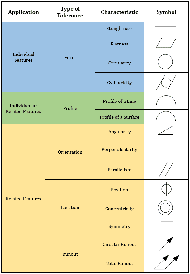
Different Types of GD&T Symbols
There are different types of GD & T symbols in engineering drawings. All the 2D and 3D product design software have features to add these symbols to drawings.
Modifiers of GD&T Symbols Use in Engineering Drawings
When we use GT&D in engineering drawings, Some modifiers can be use to modify the tolerances.

Common Other Symbols
Other than the above symbols, we can use some other symbols in Engineering Drawings. Especially Hole Symbols are very common in most of the engineering fields. e.g. Countersunk and Counterbore symbols.

Tolerance Zones for Engineering Drawings
There are some common Tolerances Zones like below.

Feature Control Frames with GD&T Symbols
Basically, Feature Control Frames are used to define the geometric tolerances of a part. The Feature Control Frame has four parts;
- GD&T Symbols and Control Symbols
- Tolerance Zone Types and Symbols
- Tolerance Zone Modifiers
- Datum References

Leader Types
When you use Feature Control Frames, You can use it with or without Leaders. Following are the common types of Leaders.

All Over Leader & All Around Leaders
Meaning of “All Over Leader” is that indicates the profile tolerance all over the three-dimensional profile of the part.

The symbolic meaning of the “All Around Leader” is that indicates profile tolerance applies to surfaces all around the profile.

Example of Feature Control Frames
Following example will give you a better understanding about Feature Control Frame

Really appreciate, taking the time to read the article about the GD&T Symbols for Engineering Drawings.
So keep in touch with MechHeart and feel free to add some comments here and share your knowledge with us.
Latest Posts


0 Comments