What is GD&T in Engineering Drawings?
GD & T is stand for Geometric Dimensioning and Tolerancing. This a very common symbolic language in many of engineering fields. Most of the time mechanical engineers are using this symbols to communicate with machine shop for CNC and manual machining. Not only that HVAC Engineers and Civil Engineers also use these GD&T in their Manufacturing and Shop Drawings. GD&T describes the nominal geometry and the permissible variation of a physical object’s features, such as size, shape, orientation, and location. Surface finish Symbol, Welding Symbol and Engineering Drawing Lines are some other engineering drawing representations.
Why you should have knowledge about GD&T?
Most of the time design engineers prepare engineering drawings and manufacturing drawings for product designs using CAD Software. Most important thing is today No One Creating Manual Drawings for Product Designs and all the designers are using Product design Software.
All the CAD software have various features to use GD&T in engineering drawings. However you should have better knowledge about GD&T to define geometrical dimensions and tolerance in engineering drawings.
Benefits of Geometric Dimensions and Tolerances
You will have lot of benefits when you are clearly define the geometric dimensions and tolerances in you drawings. Such as,
- Anyone can clearly identify the machining requirements
- Improve the quality of the final design
- Reduce the manufacturing cost due to clear GD&T
- Communicate requirements more precisely
- Easiness of collaborate with international partners and suppliers
- Compliance with Standards
GD & T Symbols
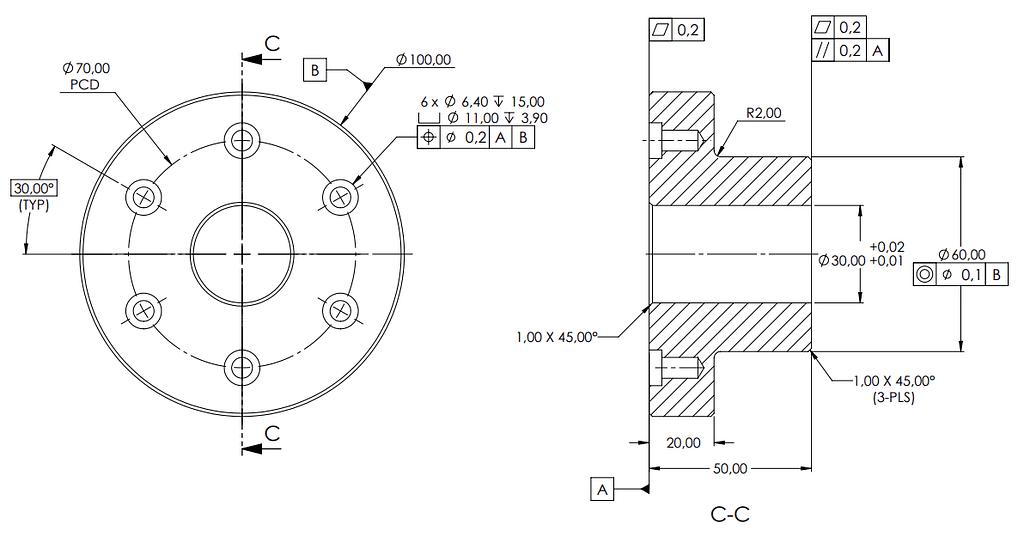
Generally all the designers should have better understanding about geometric tolerances and symbols. Otherwise you can not properly communicate your design requirement with other industrial partners. There are lot of GD&T symbols. For example followings are some GD&T in engineering drawings.
- Datum Feature
- Feature Control Frame
- Position (Positional Tolerance)
- Concentricity
- Circularity
Thank you for your time to read the article. Mechheart’s detailed GD&T Symbols article could provide valuable insights and a deeper understanding of Geometric Dimensioning and Tolerancing symbols.


0 Comments