First Angle Projection in Engineering Drawings
There are mainly two Projection Angles in Engineering Drawings. Those are Frist Angle Projection and Third Angle Projections. These projection angles are used to represent a 3D object in a 2D plan or a 2D drawing sheet. However, a 3D object represented in a 2D plane is called an Orthographic Projection.
Engineering drawings have different lines, symbols are annotations. As an example Surface Finish Symbol, Welding Symbols, and geometric tolerances. Whatever your drawing projection you will use common drawing symbols and notations.
What is First Angle Projection?
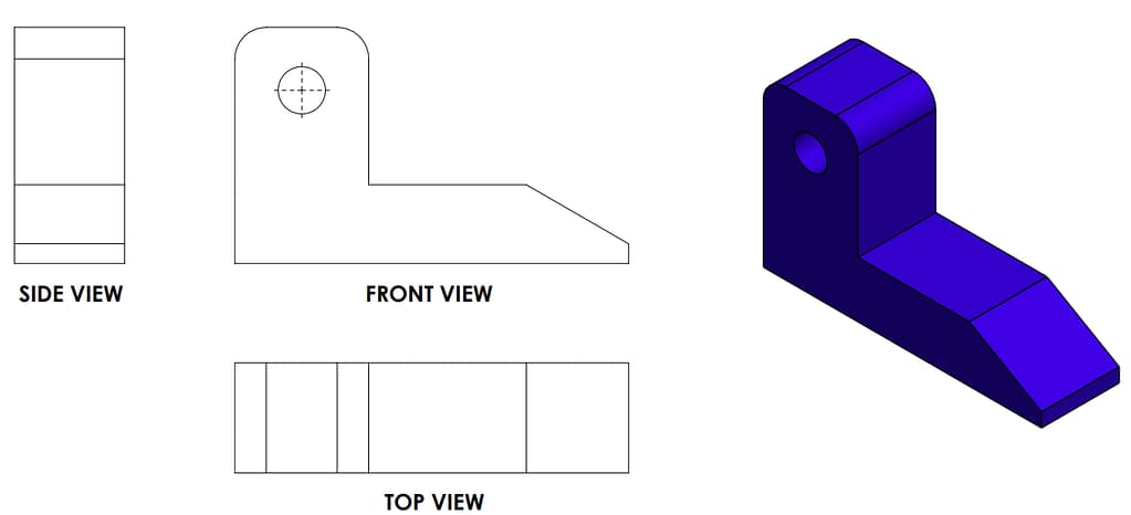
This is one of the two primary methods of projections, you can use in engineering drawing. The three main views used in first angle projection are the front view, the top view, and the side view. The front view represents the object as it appears when viewed from the front, while the top view represents the object as it would be seen from above. The side view shows the object as it would appear when viewed from the side.
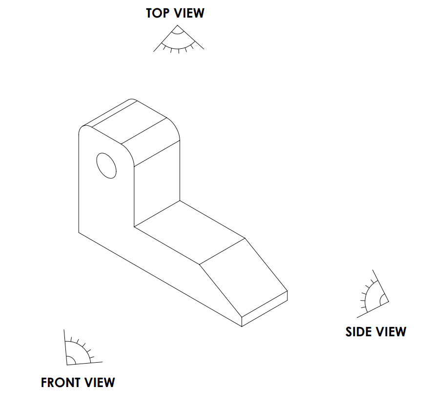
You will see a 3D object similar to this, which you can then represent in a drawing below.
Drawing Symbol
First-angle projection symbol is like this. Whatever the drawing sheets size, you need to represent the drawing angle. 1st angle or 3rd angle symbol is a must for engineering drawings. Most of the time drawing symbol is placed on the top right corner of the sheet.

Where you put your drawing symbol in the drawings. there are two common locations for the projection angle symbol. You can draw this symbol on the top left corner of the drawing or right bottom of the drawing.
Difference Between First and Third Angle Projection
Based on the countries projection angle is different. 3rd Angle is very common in the USA, UK, and some Western countries. 1st angle is very popular in Europe, Australia, and China. countries. If you are a European person most probably we will you 3rd angle. There are some differences between these projection angles.
| 1st Angle Projection | 3rd Angle Projection | |
| Object Placement | Placed in the first quadrant (top-right) | Placed in the third quadrant (bottom-left) |
| Observer’s Position | Assumed to be in the first quadrant | Views projected from the observer toward the planes |
| Projection Direction | Views projected from the observer towards the planes | Views projected as if the observer is looking through the object |
| Plane Arrangement | Front view on the frontal plane in front of the object | Front view on the frontal plane behind the object |
What is the Best Projection Angle?
You can choose a projection angle according to your interest. However, if you are working in an industry, you will use one projection angle. Most companies use one drawing angle as their company standard. It can be 1st or 3rd Angle. But you need to mention the projection angle symbol in your drawing. Then Projection Angle Symbol will help to understand the drawing.
Most of the design software has facilities for selecting projection angles. For example, Solidworks or AUTOCAD software have selection locations.
Common Practices for Engineering Drawings
Everyone follows the following common practices for engineering drawings.
- Use only one projection angle (1st or 3rd) for a drawing package.
- The projection angle symbol needs to be added to the drawing.
- Apply Geometric Tolerance (GD&T) to specify the machining requirements.


0 Comments